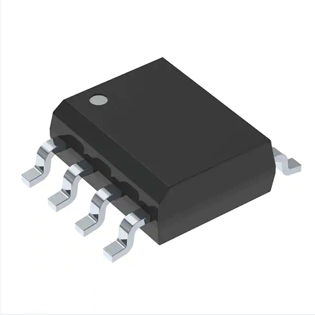
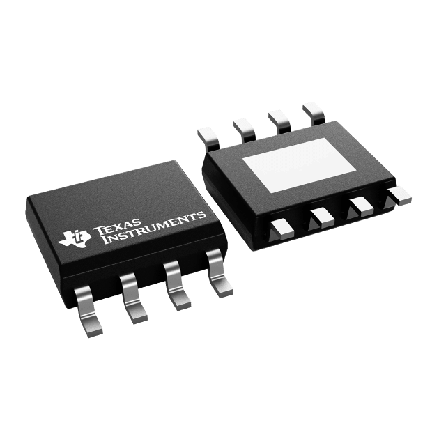
BOM Quotation Electronic Components Driver IC Chip IR2103STRPBF
Product Attributes
| TYPE | DESCRIPTION |
| Category | Integrated Circuits (ICs)
href=”https://www.digikey.sg/en/products/filter/gate-drivers/730″ Gate Drivers |
| Mfr | Infineon Technologies |
| Series | - |
| Package | Tape & Reel (TR)
Cut Tape (CT) Digi-Reel® |
| Product Status | Active |
| Driven Configuration | Half-Bridge |
| Channel Type | Independent |
| Number of Drivers | 2 |
| Gate Type | IGBT, N-Channel MOSFET |
| Voltage – Supply | 10V ~ 20V |
| Logic Voltage – VIL, VIH | 0.8V, 3V |
| Current – Peak Output (Source, Sink) | 210mA, 360mA |
| Input Type | Inverting, Non-Inverting |
| High Side Voltage – Max (Bootstrap) | 600 V |
| Rise / Fall Time (Typ) | 100ns, 50ns |
| Operating Temperature | -40°C ~ 150°C (TJ) |
| Mounting Type | Surface Mount |
| Package / Case | 8-SOIC (0.154″, 3.90mm Width) |
| Supplier Device Package | 8-SOIC |
| Base Product Number | IR2103 |
Documents & Media
| RESOURCE TYPE | LINK |
| Datasheets | IR2103(S)(PbF) |
| Other Related Documents | Part Number Guide |
| Product Training Modules | High Voltage Integrated Circuits (HVIC Gate Drivers) |
| HTML Datasheet | IR2103(S)(PbF) |
| EDA Models | IR2103STRPBF by SnapEDA |
Environmental & Export Classifications
| ATTRIBUTE | DESCRIPTION |
| RoHS Status | ROHS3 Compliant |
| Moisture Sensitivity Level (MSL) | 2 (1 Year) |
| REACH Status | REACH Unaffected |
| ECCN | EAR99 |
| HTSUS | 8542.39.0001 |
A gate driver is a power amplifier that accepts a low-power input from a controller IC and produces a high-current drive input for the gate of a high-power transistor such as an IGBT or power MOSFET. Gate drivers can be provided either on-chip or as a discrete module. In essence, a gate driver consists of a level shifter in combination with an amplifier. A gate driver IC serves as the interface between control signals (digital or analog controllers) and power switches (IGBTs, MOSFETs, SiC MOSFETs, and GaN HEMTs). An integrated gate-driver solution reduces design complexity, development time, bill of materials (BOM), and board space while improving reliability over discretely-implemented gate-drive solutions.
History
In 1989, International Rectifier (IR) introduced the first monolithic HVIC gate driver product, the high-voltage integrated circuit (HVIC) technology uses patented and proprietary monolithic structures integrating bipolar, CMOS, and lateral DMOS devices with breakdown voltages above 700 V and 1400 V for operating offset voltages of 600 V and 1200 V.[2]
Using this mixed-signal HVIC technology, both high-voltage level-shifting circuits and low-voltage analog and digital circuits can be implemented. With the ability to place high-voltage circuitry (in a ‘well’ formed by polysilicon rings), that can ‘float’ 600 V or 1200 V, on the same silicon away from the rest of the low-voltage circuitry, high-side power MOSFETs or IGBTs exist in many popular off-line circuit topologies such as buck, synchronous boost, half-bridge, full-bridge and three-phase. The HVIC gate drivers with floating switches are well-suited for topologies requiring high-side, half-bridge, and three-phase configurations.[3]
Purpose
In contrast to bipolar transistors, MOSFETs do not require constant power input, as long as they are not being switched on or off. The isolated gate-electrode of the MOSFET forms a capacitor (gate capacitor), which must be charged or discharged each time the MOSFET is switched on or off. As a transistor requires a particular gate voltage in order to switch on, the gate capacitor must be charged to at least the required gate voltage for the transistor to be switched on. Similarly, to switch the transistor off, this charge must be dissipated, i.e. the gate capacitor must be discharged.
When a transistor is switched on or off, it does not immediately switch from a non-conducting to a conducting state; and may transiently support both a high voltage and conduct a high current. Consequently, when gate current is applied to a transistor to cause it to switch, a certain amount of heat is generated which can, in some cases, be enough to destroy the transistor. Therefore, it is necessary to keep the switching time as short as possible, so as to minimize switching loss [de]. Typical switching times are in the range of microseconds. The switching time of a transistor is inversely proportional to the amount of current used to charge the gate. Therefore, switching currents are often required in the range of several hundred milliamperes, or even in the range of amperes. For typical gate voltages of approximately 10-15V, several watts of power may be required to drive the switch. When large currents are switched at high frequencies, e.g. in DC-to-DC converters or large electric motors, multiple transistors are sometimes provided in parallel, so as to provide sufficiently high switching currents and switching power.
The switching signal for a transistor is usually generated by a logic circuit or a microcontroller, which provides an output signal that typically is limited to a few milliamperes of current. Consequently, a transistor which is directly driven by such a signal would switch very slowly, with correspondingly high power loss. During switching, the gate capacitor of the transistor may draw current so quickly that it causes a current overdraw in the logic circuit or microcontroller, causing overheating which leads to permanent damage or even complete destruction of the chip. To prevent this from happening, a gate driver is provided between the microcontroller output signal and the power transistor.
Charge pumps are often used in H-Bridges in high side drivers for gate driving the high side n-channel power MOSFETs and IGBTs. These devices are used because of their good performance, but require a gate drive voltage a few volts above the power rail. When the centre of a half bridge goes low the capacitor is charged via a diode, and this charge is used to later drive the gate of the high side FET gate a few volts above the source or emitter pin’s voltage so as to switch it on. This strategy works well provided the bridge is regularly switched and avoids the complexity of having to run a separate power supply and permits the more efficient n-channel devices to be used for both high and low switches.


