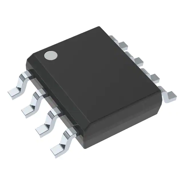
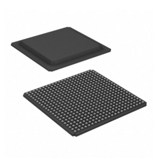
New And Orignal Iso7221cdr Intergrated Circuit IC Chip
Product Attributes
|
TYPE |
DESCRIPTION |
|
Category |
Isolators Digital Isolators |
|
Mfr |
Texas Instruments |
|
Series |
- |
|
Package |
Tape & Reel (TR) Cut Tape (CT) Digi-Reel® |
|
Product Status |
Active |
|
Technology |
Capacitive Coupling |
|
Type |
General Purpose |
|
Isolated Power |
No |
|
Number of Channels |
2 |
|
Inputs - Side 1/Side 2 |
1/1 |
|
Channel Type |
Unidirectional |
|
Voltage - Isolation |
2500Vrms |
|
Common Mode Transient Immunity (Min) |
25kV/µs |
|
Data Rate |
25Mbps |
|
Propagation Delay tpLH / tpHL (Max) |
42ns, 42ns |
|
Pulse Width Distortion (Max) |
2ns |
|
Rise / Fall Time (Typ) |
1ns, 1ns |
|
Voltage - Supply |
2.8V ~ 5.5V |
|
Operating Temperature |
-40°C ~ 125°C |
|
Mounting Type |
Surface Mount |
|
Package / Case |
8-SOIC (0.154", 3.90mm Width) |
|
Supplier Device Package |
8-SOIC |
|
Base Product Number |
ISO7221 |
|
SPQ |
2500/pcs |
Introduction
A digital isolator is a chip in an electronic system in which digital and analog signals are transmitted, so that they have high resistance isolation characteristics to achieve isolation between the electronic system and the user. Designers introduce isolation to meet safety regulations or to reduce the noise of the ground loop. Galvanic isolation ensures that data transmission is not through electrical connections or leakage paths, thus avoiding safety risks. However, isolation imposes limitations on latency, power consumption, cost, and size. The goal of digital isolators is to meet safety requirements while minimizing adverse effects.
Features
1, 5, 25, and 150-Mbps Signaling Rate Options
1.Low Channel-to-Channel Output Skew; 1-ns Max
2.Low Pulse-Width Distortion (PWD); 1-ns Max
3.Low Jitter Content; 1 ns Typ at 150 Mbps
50 kV/µs Typical Transient Immunity
Operates with 2.8-V (C-Grade), 3.3-V, or 5-V Supplies
4-kV ESD Protection
High Electromagnetic Immunity
–40°C to +125°C Operating Range
Typical 28-Year Life at Rated Voltage (see High-Voltage Lifetime of the ISO72x Family of Digital Isolators and Isolation Capacitor Lifetime Projection)
Safety-Related Certifications
1.VDE Basic Insulation with 4000-VPK VIOTM, 560 VPK VIORM per DIN VDE V 0884-11:2017-01 and DIN EN 61010-1 (VDE 0411-1)
2.2500 VRMS Isolation per UL 1577
3.CSA Approved for IEC 60950-1 and IEC 62368-1
Product Description
A binary input signal is conditioned, translated to a balanced signal, then differentiated by the capacitive isolation barrier. Across the isolation barrier, a differential comparator receives the logic transition information, then sets or resets a flip-flop and the output circuit accordingly. A periodic update pulse is sent across the barrier to ensure the proper dc level of the output. If this dc-refresh pulse is not received every 4 µs, the input is assumed to be unpowered or not being actively driven, and the failsafe circuit drives the output to a logic high state.
The small capacitance and resulting time constant provide fast operation with signaling rates available from 0 Mbps (DC) to 150 Mbps (The signaling rate of a line is the number of voltage transitions that are made per second expressed in the units bps). The A-option, B-option, and C-option devices have TTL input thresholds and a noise filter at the input that prevents transient pulses from being passed to the output of the device. The M-option devices have CMOS VCC/2 input thresholds and do not have the input noise filter and the additional propagation delay.
The ISO7220x and ISO7221x family of devices require two supply voltages of 2.8 V (C-Grade), 3.3 V, 5 V, or any combination. All inputs are 5-V tolerant when supplied from a 2.8-V or 3.3-V supply and all outputs are 4-mA CMOS.
The ISO7220x and ISO7221x family of devices are characterized for operation over the ambient temperature range of –40°C to +125°C.


